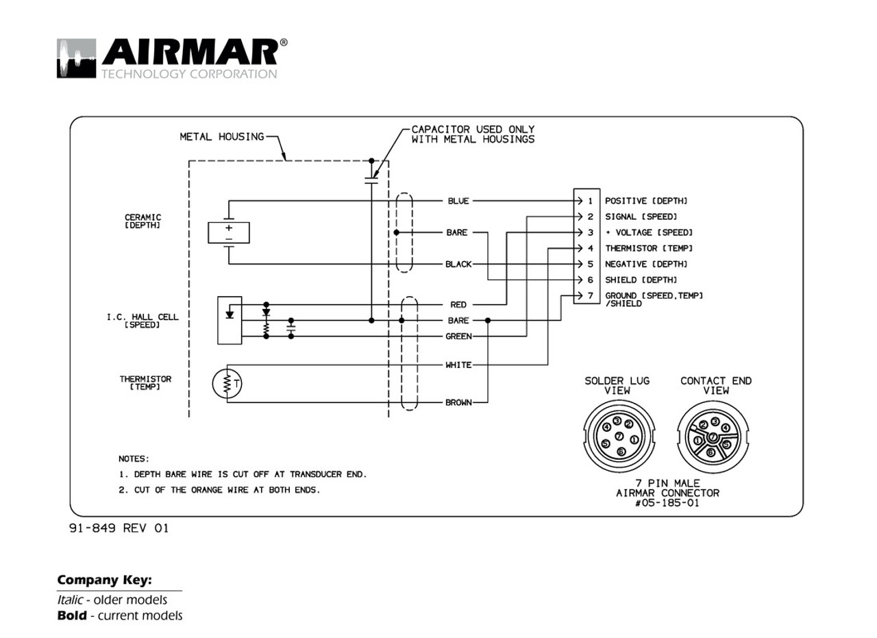
Humminbird Transducer Wiring Diagram
All circuits are usually the same voltage ground solitary component and switches. Airmars transducer cross reference offers a variety of transducer informationfrom wiring diagrams to sounder compatibility and more.
Https Www Humminbird Com Sites Humminbird Site Files Rigging Diagram 4 Pdf
Universal Sonar 2s state- of-the-art integrated and protected transducer is built into the HUMMINBIRD HELIX SERIES.
Humminbird transducer wiring diagram. Figure Transom Transducer Installation. 5 Bolt the transducer to the galvanized T using the two lock washers and the 3 x 14 SS bolt Fig 1-2. Raymarine unit uses 2 wires plus screen.
Most people dont get them because they dread the installation processwhen we first started out we had multiple online guides to help install the fish finder. Smart Load Cell Systems Buy Online or Call 800-344-3965. Easy installation all hardware included.
Low profile design minimize snags. Install an inline fuse holder not included and the required fuse as shown in the Required Fuse Size table. Transducer and external Garmin GPSMap 76 series.
HB cable wiring diagrams 2. Re-stating the obvious your transducer is not working but you know that the sounder is. The depth transducer has 5 pins but the matrix 12 unit only uses 3 of them.
Then tighten the nuts an additional 2 full revolutions. Installation is shown with a GPS heading sensor and additional High Speed Transducer. Down ImagingDualBeam Plus 7545 455800 kHz DI and 2516 200455 kHz with built in temperature 15 Cable.
HB cable wiring diagrams 2. DOWNLOAD DIAGRAM 2 FOR. If so you can simply.
I am adding the 2D transducer to the. On Humminbird Piranha 20 Transducer Wiring Diagram. The raymarine shows 4 wires plus screen to be connected.
On Humminbird Transducer Wiring Diagram. Wiring color code diagram for Transducer Techniques Load Cells available online for download or viewing come checkout other online services. INSTALLATION DIAGRAMS Console Bow Mount Humminbird Units The following schematic outlines the necessary accessoriescables needed to connect two Humminbird units.
DOWNLOAD DIAGRAM 1 FOR. Cable wiring diagrams showing pin outs. Humminbird Transducer Wiring Diagram Source.
Humminbird Transducer Wiring Diagram. A wiring diagram is a streamlined traditional photographic depiction of an electrical circuit. Wiring Diagrams for Conventional non-CHIRP Transducers Check to see if the transducer is a Mix and Match W or 1kW model.
1 Humminbird bow unit and 1 console unit networked together with heading sensor GPS puck and high-speed transducer with y-cable. DOWNLOAD DIAGRAM 3 FOR. Also requires Lowrance adapter cable part number These diagrams are for the use of professional installers.
Humminbird has built its reputation by designing and manufacturing installation and operations manual carefully in order to get full benefit from all PiranhaMAX - Dual Beam V x H Monochrome Display Mounting the Assembly to the Transom. Install the required fuse as shown in the Required Fuse Size table. Enter any of the following into the search box.
Attach the black wire to ground and the red wire to positive. Heres the diagram for AS PC2 Connect Cable if you want to make your own. From under the deck or gunwale install the 14 fender washer and the 14-20 nylon insert hex nut not included onto each screw.
Minn Kota Trolling Motor with i-Pilot Link and Built-in MEGA Imaging 1 bow-mounted Humminbird unit and 1 console mounted Humminbird unit. AS PC2 Connect Wiring Diagram. If there is too much slop in the transducer bolt attachment then rubber or similar material sleeves can be positioned on the inside of the bolt.
Just enter the first few numbers of the part number and see the results immediately. Adjust the transducer assembly vertically until the seam on the leading edge of the transducer see 1 below is level and just slightly below the hull. Attach the black wire to ground and the red wire to positive 12 VDC power.
Hi Greg and Ernesto. Trolling Motor Mount Transducer. An illustrated manual transducer attachment and wiring a Garmin GPS to the Humminbird control head.
XTM 9 WIDE DI 20 T. Transducer to the end of the galvanized pipe Fig. Adjust the initial angle of the transducer from back to front by rotating the transducer until the side seam on the transducer is almost parallel with the bottom of the boat one click at a.
Trolling Motor Mount Transducer. The speedo has 4 pins coming out of transducer. Use an adjustable socket or wrench to hand-tighten the nuts until they contact the washers.
Before attempting to rewire a transducer.

Airmar Wiring Diagram Furuno 10 Pin Best Deal Blue Bottle Marine

4 Wire Pressure Transducer Wiring Diagram Transducer Wiring Diagram Diagram

How Do I Connect The Three Wires On The Power Cable Of My Mega 360 Humminbird

Garmin Transducer Wiring Diagram Ciktutor

Garmin Transducer Wiring Diagram Ciktutor

Garmin Transducer Wiring Diagram Ciktutor
Diagram Garmin 160 Fishfinder Wiring Diagram Full Version Hd Quality Wiring Diagram Mediagrame Teatrodelloppresso It

Airmar Wiring Diagram Garmin 6 Pin D Best Deal Blue Bottle Marine

New Raymarine Dragonfly 4dv W T M Transducer Chirp Downvision Sonar E7029 Raymarine Dragonfly Transducer Marine Electronics

Airmar Wiring Diagram Lowrance Simrad 7 Pin D S T Best Deal Blue Bottle Marine
Helix 7 Chirp Mega Si Mega Di G3n Transducer Cable Colored Wires

Motorguide Trolling Motor Trolling Motor Wiring Diagram

Humminbird Xfm 9 20 Plastic Flush Mount Thru Hull Transducer By Humminbird 82 18 Amazon Com The Humminb Humminbird Transducer Tracking Device

Airmar Wiring Diagram Navman Northstar 6 Pin Best Deal Blue Bottle Marine

How Do You Wire A Garmin Striker 4 In 2021 Kayak Fishing Diy Kayak Fishing Kayak Fishing Setup

Minn Kota Terrova Main Control Board Part Number 2774016 12 Volt Minn Kota Boat Parts Control

Humminbird Smartcast Rf45 Advance Remote Sonar Sensor By Humminbird 24 20 Amazon Com With The Humminbird Rf45 A In 2021 Humminbird Fish Finder Sensor

